-
×
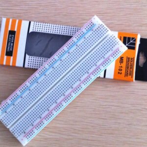 Breadboard MB102
1 × 300 L
Breadboard MB102
1 × 300 L
Nënshumë: 300 L
Analog joystick sensor arduino
300 L
Analog joystick sensor arduino
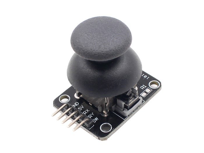
Analog joystick sensor arduino Analog Joystick Sensor: Image credit to MakerFabs
The following article is structured like so:
Overview: Input & Output pins of the joystick
Understanding a Joystick: How a joystick works
Connecting it to an Arduino: Step-by-step wiring
Demo + How to Code: Creating the demo
(Disclaimer: These tutorials were made by my wonderful team and I. The following has been edited slightly for sharing.)
Overview
The joystick is useful for reading and interpreting 2D motion through two analog variables, which represent the position of the sensor on a 2D plane. The joystick can also be pressed inwards like a button, which is useful for functions such as selecting items in menus.
Input 1: Moving the stick
Output 1: position of handle relative to its center, X and Y axis
Input 2: Pressing the button
Output 2: Whether the button is pressed or not
Understanding a Joystick
Before we go in to how to connect a sensor and use it in code, it is important to understand how a joystick works internally.
The analog joystick has a handle and two slotted shafts around the handle (along the x-axis and y-axis). The handle can be pushed to any point in a plane, which will cause one or both of the slotted shafts to pivot. Each slotted shaft is attached to a potentiometer on the side, which converts the angular displacement of the shaft to an analog signal.
The data for each axis is determined in analog using a potentiometer, communicating position in the form of voltage. This is possible because the shaft is connected to a wiper and resistive strip inside the potentiometer.
Resistive strip controlling output voltage
As the wiper moves further along the resistive strip, more current passes through the strip to complete the circuit, thereby increasing the total resistance of the circuit.
Therefore, twisting the potentiometer will change the voltage of its output. In its default position along an axis, the joystick will output half the voltage input. As we move along an axis, the voltage of the output will move either to the maximum inputted voltage, or to zero, signaling how far we have moved the shaft of the joystick.
Connecting it to an Arduino
Here are what the 5 pins of the analog joystick mean:
GND: Ground
+5V: 5V power source
VRx: X-direction reading (Analog)
VRy: Y-direction reading (Analog)
SW: Button press (Digital)
VRx and VRy should be connected to analog pins on the Arduino, and SW should be connected to a digital pin. As usual, +5V should be connected to 5V, and the GND pin should be connected to GND.
Step by Step Instructions
1. GND: Place one end of a wire at the GND pin on the joystick to the GND pin on the arduino (Black Wire)
2. +5V: Place one end of a wire at the 5V source pin on the joystick (+5V) to the 5V pin on the arduino (Red Wire)
3. VRx: Place one end of a wire at the VRx pin on the joystick to any analog pin on the arduino (Orange Wire — We connected it to pin A3)
4. VRy: Place one end of a wire at the VRy pin on the joystick to any analog pin on the arduino (Yellow Wire — We connected it to pin A1)
5. SW: Place one end of a wire at the SW pin on the joystick to any digital pin on the arduino. (Sky Blue Wire — We connected it to pin D5)
The Arduino Mega 2560 is a microcontroller board based on the ATmega2560. It has 54 digital input/output pins (of which 15 can be used as PWM outputs), 16 analog inputs, 4 UARTs (hardware serial ports), a 16 MHz crystal oscillator, a USB connection, a power jack, an ICSP header, and a reset button. It contains everything needed to support the microcontroller; simply connect it to a computer with a USB cable or power it with a AC-to-DC adapter or battery to get started. The Mega 2560 board is compatible with most shields designed for the Uno and the former boards Duemilanove or Diecimila.
The HC–SR04 ultrasonic sensor uses sonar to determine distance to an object like bats do. It offers excellent non-contact range detection with high accuracy and stable readings in an easy-to-use package. From 2 cm to 400 cm or 1” to 13 feet. Ultrasonic sensors are used typically in applications to measure the level or the distance. Especially in the level measurement ultrasonic sensors are used because they are quick and easy to implement.


There are no reviews yet.